
Graph Algorithms

The Graph Theory has important applications in Critical path analysis, Social psychology, Matrix theory, Set theory, Topology, Group theory, Molecular chemistry, and Searching.
Those who would like to take a quick tour of essentials of graph theory please go directly to "Graph Theory" from here.
has vertex set V and edge set E where: V = {1,2,3,4} and E = {(1,2),(2,4),(4,3),(3,1),(1,4),(2,1),(4,2),(3,4),(1,3),(4,1). Notice that each edge seems to be listed twice.
Proof (by contradiction) Suppose component graph of G = (V, E) was not a DAG and G comprised of a cycle consisting of vertices v1, v2 , . . . , vn . Each vi corresponds to a strongly connected component (SCC) of component graph G. If v1, v2 , . . . , vn themselves form a cycle then each vi ( i runs from 1 to n) should have been included in the SCC corresponding to vj ( j runs from 1 to n and i ≠ j). But each of the vertices is a vertex from a difference SCC of G. Hence, we have a contradiction! Therefore, SCC of G is a directed acyclic graph.
The edges of A will form a rooted tree with root r :
Bellman-Ford algorithm solves the single-source shortest-path problem in the general case in which edges of a given digraph can have negative weight as long as G contains no negative cycles.
This algorithm, like Dijkstra's algorithm uses the notion of edge relaxation but does not use with greedy method. Again, it uses d[u] as an upper bound on the distance d[u, v] from u to v.
The algorithm progressively decreases an estimate d[v] on the weight of the shortest path from the source vertex s to each vertex v in V until it achieve the actual shortest-path. The algorithm returns Boolean TRUE if the given digraph contains no negative cycles that are reachable from source vertex s otherwise it returns Boolean FALSE.
- Breadth First Search (BFS)
- Depth First Search (DFS)
- Topological Sort
- Strongly Connected Components
- Euler Tour
- Generic Minimum Spanning Tree
- Kruskal's Algorithm
- Prim's Algorithm
- Single Source Shortest Path
- Dijkstra's Algorithm
- Bellman-Ford Algorithm
Graph Algorithms
Graph Theory is an area of mathematics that deals with following types of problems
- Connection problems
- Scheduling problems
- Transportation problems
- Network analysis
- Games and Puzzles.
The Graph Theory has important applications in Critical path analysis, Social psychology, Matrix theory, Set theory, Topology, Group theory, Molecular chemistry, and Searching.
Those who would like to take a quick tour of essentials of graph theory please go directly to "Graph Theory" from here.
Digraph
A directed graph, or digraph G consists of a finite nonempty set of vertices V, and a finite set of edges E, where an edge is an ordered pair of vertices in V. Vertices are also commonly referred to as nodes. Edges are sometimes referred to as arcs.
As an example, we could define a graph G=(V, E) as follows:
As an example, we could define a graph G=(V, E) as follows:
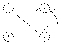
V = {1, 2, 3, 4}
E = { (1, 2), (2, 4), (4, 2) (4, 1)}
E = { (1, 2), (2, 4), (4, 2) (4, 1)}
Here is a pictorial representation of this graph.
The definition of graph implies that a graph can be drawn just knowing its vertex-set and its edge-set. For example, our first example
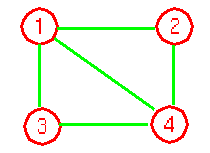
has vertex set V and edge set E where: V = {1,2,3,4} and E = {(1,2),(2,4),(4,3),(3,1),(1,4),(2,1),(4,2),(3,4),(1,3),(4,1). Notice that each edge seems to be listed twice.
Another example, the following Petersen Graph G=(V,E) has vertex set V and edge set E where: V = {1,2,3,4}and E ={(1,2),(2,4),(4,3),(3,1),(1,4),(2,1),(4,2),(3,4),(1,3),(4,1)}.
We'll quickly covers following three important topics from algorithmic perspective.
- Transpose
- Square
- Incidence Matrix
1. Transpose
If graph G = (V, E) is a directed graph, its transpose, GT = (V, ET) is the same as graph G with all arrows reversed. We define the transpose of a adjacency matrix A = (aij) to be the adjacency matrix AT = (Taij) given by Taij = aji. In other words, rows of matrix A become columns of matrix AT and columns of matrix A becomes rows of matrix AT. Since in an undirected graph, (u, v) and (v, u) represented the same edge, the adjacency matrix A of an undirected graph is its own transpose: A = AT.
Formally, the transpose of a directed graph G = (V, E) is the graph GT (V, ET), where ET = {(u, v) Î V×V : (u, v)ÎE. Thus, GT is G with all its edges reversed.
We can compute GT from G in the adjacency matrix representations and adjacency list representations of graph G.
Algorithm for computing GT from G in representation of graph G is
ALGORITHM MATRIX TRANSPOSE (G, GT)
For i = 0 to i < V[G]
For j = 0 to j V[G]
GT (j, i) = G(i, j)
j = j + 1;
i = i + 1
To see why it works notice that if GT(i, j) is equal to G(j, i), the same thing is achieved. The time complexity is clearly O(V2).
Algorithm for Computing GT from G in Adjacency-List Representation
In this representation, a new adjacency list must be constructed for transpose of G. Every list in adjacency list is scanned. While scanning adjacency list of v (say), if we encounter u, we put v in adjacency-list of u.
ALGORITHM LIST TRANSPOSE [G]
for u = 1 to V[G]
for each element vÎAdj[u]
Insert u into the front of Adj[v]
To see why it works, notice if an edge exists from u to v, i.e., v is in the adjacency list of u, then u is present in the adjacency list of v in the transpose of G.
2. Square
The square of a directed graph G = (V, E) is the graph G2 = (V, E2) such that (a, b)ÎE2 if and only if for some vertex cÎV, both (u, c)ÎE and (c,b)ÎE. That is, G2 contains an edge between vertex a and vertex b whenever G contains a path with exactly two edges between vertex a and vertex b.
Algorithms for Computing G2 from G in the Adjacency-List Representation of G
Create a new array Adj'(A), indexed by V[G]
For each v in V[G] do
For each u in Adj[v] do
\\ v has a path of length 2.
\\ to each of the neighbors of u
make a copy of Adj[u] and append it to Adj'[v]
Return Adj'(A).
For each vertex, we must make a copy of at most |E| list elements. The total time is O(|V| * |E|).
Algorithm for Computing G2 from G in the Adjacency-Matrix representation of G.
For i = 1 to V[G]
For j = 1 to V[G]
For k = 1 to V[G]
c[i, j] = c[i, j] + c[i, k] * c[k, j]
Because of three nested loops, the running time is O(V3).
3. Incidence Matrix
The incidence matrix of a directed graph G=(V, E) is a V×E matrix B = (bij) such that
-1 if edge j leaves vertex j.
bij = 1 if edge j enters vertex j.
0 otherwise.
If B is the incidence matrix and BT is its transpose, the diagonal of the product matrix BBT represents the degree of all the nodes, i.e., if P is the product matrix BBT then P[i, j] represents the degree of node i:
Specifically we have
BBT(i,j) = ∑eÎE bie bTej = ∑eÎE bie bje
Now,
- If i = j, then biebje = 1, whenever edge e enters or leaves vertex i and 0 otherwise.
- If i ≠ j, then biebje = -1, when e = (i, j) or e = (j, i) and 0 otherwise.
Therefore
BBT(i,j) = deg(i) = in_deg + Out_deg if i = j
= -(# of edges connecting i an j ) if i ≠ j
Breadth-First Search Traversal Algorithm
Breadth-first search is a way to find all the vertices reachable from the a given source vertex, s. Like depth first search, BFS traverse a connected component of a given graph and defines a spanning tree. Intuitively, the basic idea of the breath-first search is this: send a wave out from source s. The wave hits all vertices 1 edge from s. From there, the wave hits all vertices 2 edges from s. Etc. We use FIFO queue Q to maintain the wavefront: v is in Q if and only if wave has hit v but has not come out of v yet.
Overall Strategy of BFS Algorithm
Breadth-first search starts at a given vertex s, which is at level 0. In the first stage, we visit all the vertices that are at the distance of one edge away. When we visit there, we paint as "visited," the vertices adjacent to the start vertex s - these vertices are placed into level 1. In the second stage, we visit all the new vertices we can reach at the distance of two edges away from the source vertex s. These new vertices, which are adjacent to level 1 vertices and not previously assigned to a level, are placed into level 2, and so on. The BFS traversal terminates when every vertex has been visited.
To keep track of progress, breadth-first-search colors each vertex. Each vertex of the graph is in one of three states:
1. Undiscovered;
2. Discovered but not fully explored; and
3. Fully explored.
2. Discovered but not fully explored; and
3. Fully explored.
The state of a vertex, u, is stored in a color variable as follows:
1. color[u] = White - for the "undiscovered" state,
2. color [u] = Gray - for the "discovered but not fully explored" state, and
3. color [u] = Black - for the "fully explored" state.
2. color [u] = Gray - for the "discovered but not fully explored" state, and
3. color [u] = Black - for the "fully explored" state.
The BFS(G, s) algorithm develops a breadth-first search tree with the source vertex, s, as its root. The parent or predecessor of any other vertex in the tree is the vertex from which it was first discovered. For each vertex, v, the parent of v is placed in the variable π[v]. Another variable, d[v], computed by BFS contains the number of tree edges on the path from s to v. The breadth-first search uses a FIFO queue, Q, to store gray vertices.
Algorithm: Breadth-First Search Traversal
BFS(V, E, s)
1. for each u in V − {s} ▷ for each vertex u in V[G] except s.
2. do color[u] ← WHITE
3. d[u] ← infinity
4. π[u] ← NIL
5. color[s] ← GRAY ▷ Source vertex discovered
6. d[s] ← 0 ▷ initialize
7. π[s] ← NIL ▷ initialize
8. Q ← {} ▷ Clear queue Q
9. ENQUEUE(Q, s)
10 while Q is non-empty
11. do u ← DEQUEUE(Q) ▷ That is, u = head[Q]
12. for each v adjacent to u ▷ for loop for every node along with edge.
13. do if color[v] ← WHITE ▷ if color is white you've never seen it before
14. then color[v] ← GRAY
15. d[v] ← d[u] + 1
16. π[v] ← u
17. ENQUEUE(Q, v)
18. DEQUEUE(Q)
19. color[u] ← BLACK
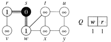
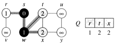
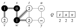
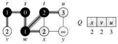
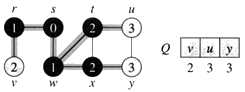
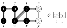
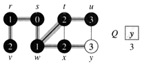
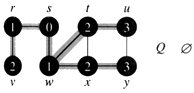
Example: The following figure (from CLRS) illustrates the progress of breadth-first search on the undirected sample graph.
a. After initialization (paint every vertex white, set d[u] to infinity for each vertex u, and set the parent of every vertex to be NIL), the source vertex is discovered in line 5. Lines 8-9 initialize Q to contain just the source vertex s.
b. The algorithm discovers all vertices 1 edge from s i.e., discovered all vertices (w and r) at level 1.
c.
d. The algorithm discovers all vertices 2 edges from s i.e., discovered all vertices (t, x, and v) at level 2.
e.
f.
g. The algorithm discovers all vertices 3 edges from s i.e., discovered all vertices (u and y) at level 3.
h.
i. The algorithm terminates when every vertex has been fully explored.
Analysis
- The while-loop in breadth-first search is executed at most |V| times. The reason is that every vertex enqueued at most once. So, we have O(V).
- The for-loop inside the while-loop is executed at most |E| times if G is a directed graph or 2|E| times if G is undirected. The reason is that every vertex dequeued at most once and we examine (u, v) only when u is dequeued. Therefore, every edge examined at most once if directed, at most twice if undirected. So, we have O(E).
Therefore, the total running time for breadth-first search traversal is O(V + E).
Lemma 22.3 (CLRS) At any time during the execution of BFS suppose that Q contains the vertices {v1, v2, ..., vr} with v1 at the head and vr at the tail. Then d[v1] ≤ d[v2] ≤ ... ≤ d[vr] ≤ d[v1] + 1.
Let v be any vertex in V[G]. If v is reachable from s then let δ(s, v) be the minimum number of edges in E[G] that must be traversed to go from vertex s to vertex v. If v is not reachable from s then let δ(s, v) = ∞.
Theorem 22.5 (CLRS) If BFS is run on graph G from a source vertex s in V[G] then for all v in V[G], d[v] = δ(s, v) and if v ≠ s is reachable from s then one of the shortest paths from s to v is a shortest path from s to π[v] followed by the edge from π[v] to v.
BFS builds a tree called a breadth-first-tree containing all vertices reachable from s. The set of edges in the tree (called tree edges) contain (π[v], v) for all v where π[v] ≠ NIL.
If v is reachable from s then there is a unique path of tree edges from s to v. Print-Path(G, s, v) prints the vertices along that path in O(|V|) time.
Print-Path(G, s, v)
if v = s
then print s
else if π[v] ← NIL
then print "no path exists from " s "to" v"
else Print-Path(G, s, π[v])
print v
then print s
else if π[v] ← NIL
then print "no path exists from " s "to" v"
else Print-Path(G, s, π[v])
print v
Algorithms based on BFS
Based upon the BFS, there are O(V + E)-time algorithms for the following problems:
- Testing whether graph is connected.
- Computing a spanning forest of graph.
- Computing, for every vertex in graph, a path with the minimum number of edges between start vertex and current vertex or reporting that no such path exists.
- Computing a cycle in graph or reporting that no such cycle exists.
In our course, we will use BFS in the following:
- Prim's MST algorithm. (CLRS, Chapter 23.)
- Dijkstra's single source shortest path algorithm. (CLRS, Chapter 24.)
Some Applications of BFS
1. Bipartite Graph
We define bipartite graph as follows: A bipartite graph is an undirected graph G = (V, E) in which V can be partitioned into two sets V1 and V2 such that (u, v) E implies either u in V1 and v in V2 or u in V2 and v in V1. That is, all edges go between the two sets V1 and V2.
In other to determine if a graph G = (V, E) is bipartite, we perform a BFS on it with a little modification such that whenever the BFS is at a vertex u and encounters a vertexv that is already 'gray' our modified BSF should check to see if the depth of both u and v are even, or if they are both odd. If either of these conditions holds which implies d[u] and d[v] have the same parity, then the graph is not bipartite. Note that this modification does not change the running time of BFS and remains O(V + E).
Formally, to check if the given graph is bipartite, the algorithm traverse the graph labeling the vertices 0, 1, or 2 corresponding to unvisited, partition 1 and partition 2 nodes. If an edge is detected between two vertices in the same partition, the algorithm returns.
ALGORITHM: BIPARTITE (G, S)
For each vertex u in V[G] − {s}
do color[u] ← WHITE
d[u] ← ∞
partition[u] ← 0
color[s] ← GRAY
partition[s] ← 1
d[s] ← 0
Q ← [s]
while Queue 'Q' is non-empty
do u ← head [Q]
for each v in Adj[u] do
if partition [u] ← partition [v]
then return 0
else
if color[v] ← WHITE then
then color[v] ← gray
d[v] = d[u] + 1
partition[v] ← 3 − partition[u]
ENQUEUE (Q, v)
DEQUEUE (Q)
Color[u] ← BLACK
Return 1
Correctness
As Bipartite (G, S) traverse the graph it labels the vertices with a partition number consisted with the graph being bipartite. If at any vertex, algorithm detects an inconsistency, it shows with an invalid return value. Partition value of u will always be a valid number as it was enqueued at some point and its partition was assigned at that point. At line 19, partition of v will unchanged if it already set, otherwise it will be set to a value opposite to that of vertex u.
Analysis
The lines added to BFS algorithm take constant time to execute and so the running time is the same as that of BFS which is O(V + E).
2. Diameter of Tree
The diameter of a tree T = (V, E) is the largest of all shortest-path distance in the tree and given by max[dist(u, v)]. As we have mentioned that BSF can be use to compute, for every vertex in graph, a path with the minimum number of edges between start vertex and current vertex. It is quite easy to compute the diameter of a tree. For each vertex in the tree, we use BFS algorithm to get a shortest-path. By using a global variable length, we record the largest of all shortest-paths.
ALGORITHM: TREE_DIAMETER (T)
maxlength ← 0
for s ← 0 to s < |V[T]|
do temp ← BSF(T, S)
if maxlength < temp
maxlength ← temp
increment s by 1
return maxlength
for s ← 0 to s < |V[T]|
do temp ← BSF(T, S)
if maxlength < temp
maxlength ← temp
increment s by 1
return maxlength
Analysis
This will clearly takes O(V(V + E)) time.
Topological Sort
A cycle in a diagraph or directed graph G is a set of edges, {(v1, v2), (v2, v3), ..., (vr −1, vr)} where v1 = vr. A diagraph is acyclic if it has no cycles. Such a graph is often referred to as a directed acyclic graph, or DAG, for short. DAGs are used in many applications to indicate precedence among events. For example, applications of DAGs include the following:
- Inheritance between C++ classes or Java interfaces.
- Prerequisites between courses of a degree program.
- Scheduling constraints between the tasks of a projects.
Thus, a DAG is good for modeling processes and structures that have a partial order: a > b and b > c imply a > c. But may have a and b such that neither a > b or b > a.
One can always make a total order (either a > b or b > a for all a ≠ b) from a partial order. In fact, that's what a topological sort will do.
Lemma 22.11 A directed graph G is acyclic if and only if a depth-first search of G yields no back edges.
Proof First, we argue the necessity (the "only if" part of the statement). That is, show that back edge implies cycle.
Suppose there is a back edge (u, v). Then v is ancestor of u in depth-first forest. Therefore, there is a path from v to u, so v to u to v is a cycle.
Now, we argue the sufficiency (the "if" part of the statement). That is, show that cycle implies back edge. Suppose G contains cycle c. Let v be the first vertex discovered inc, and let (u, v) be the preceding edge in c. At time d[u], vertices of c form a white path from v to u (since v is the first vertex discovered in c). By white-path theorem, u is descendant of v in depth-first forest. Therefore, (u, v) is a back edge. And this completes the proof.
The vertices of a DAG can be ordered in such a way that every edge goes from an earlier vertex to a later vertex. This is called a topological sort or topological ordering. Formally, we say a topological sort of a directed acyclic graph G is an ordering of the vertices of G such that for every edge (vi, vj) of G we have i < j. That is, a topological sort is a linear ordering of all its vertices such that if DAG G contains an edge (vi, vj), then vi appears before vj in the ordering. If DAG is cyclic then no linear ordering is possible. In simple words, a topological ordering is an ordering such that any directed path in DAG G traverses vertices in increasing order. It is important to note that if the graph is not acyclic, then no linear ordering is possible. That is, we must not have circularities in the directed graph. For example, in order to get a job you need to have work experience, but in order to get work experience you need to have a job (sounds familiar?)
Note that a diagraph may have several different topological sorts. Thus, topological sort is different from the usual kind of "sorting" studied in part 1 of this course.
One way to get a topological sort of a DAG is to run a depth-first search and then order the vertices so their f time-stamps are in descending order. This requires Θ(|V| lg |V|) time if a comparison sort algorithm is used.
One can modify the depth-first search of a DAG to produce a topological sort. When a vertex changes to black push it on a stack or put it on the front of a linked list. In which case, the running time is Θ(|V| + |E|).
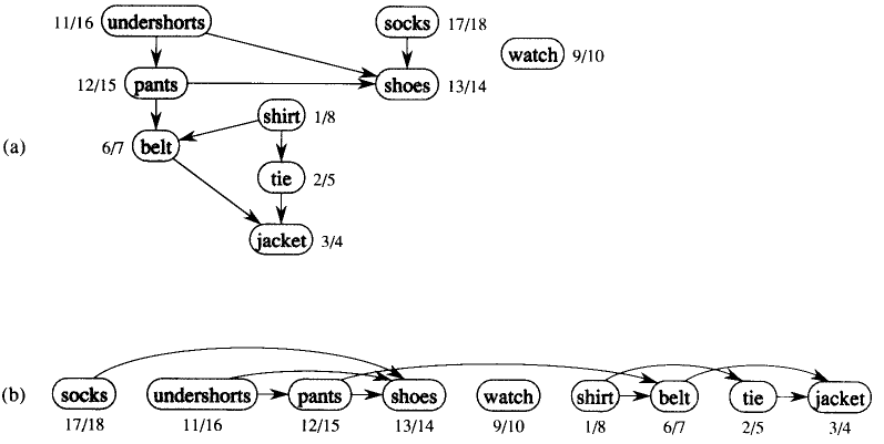
Example: The following figure (CLRS-Figure 22.7) gives an example that arises when Professor Bumstead gets dressed in the morning. The DAG of dependencies for putting clothing is given (not shown in the figure). (a) The discovery and finishing times from depth-first search are shown next to each vertex. (b) Then the same DAG shown topologically sorted.
Topological sort of a DAG: a linear ordering of vertices such that if (u, v) in E, then u appears somewhere before v. (Certainly not like sorting numbers.)
TOPOLOGICAL-SORT(V, E)
Call DFS(V, E) to compute finishing times f[v] for all v in V
Output vertices in order of decreasing finish times
Output vertices in order of decreasing finish times
It should be clear from above discussion that we don't need to sort by finish times.
- We can just output vertices as they are finished and understand that we want the reverse of this list.
- Or we can put vertices onto the front of a linked list as they are finished. When done, the list contains vertices in topologically sorted order.
Example: From the example above.
Order of vertices:
18 socks
16 underpants
15 pants
14 shoes
10 watch
8 shirt
7 belt
5 tie
4 jacket
16 underpants
15 pants
14 shoes
10 watch
8 shirt
7 belt
5 tie
4 jacket
Correctness
To established the correctness, we just need to show if (u, v) in E, then f[v] < f[u]. When we explore (u, v), what are the colors of u and v?
The vertex u is gray. Now the first question is: Is v gray, too? The answer is "no", because then v would be ancestor of u. Which implies (u, v) is a back edge. But this contradicts the previous lemma (DAG has no back edges). The second question is: Is v white? If v is white then v becomes descendant of u. By parenthesis theorem, d[u] < d[v] < f[v] < f[u]. The third question is: Is v black? If v is black, then v is already finished. Since, we are exploring (u, v), we have not yet finished u. Therefore, f[v] < f[u].
Strongly Connected Components
Decomposing a directed graph into its strongly connected components is a classic application of depth-first search. The problem of finding connected components is at the heart of many graph application. Generally speaking, the connected components of the graph correspond to different classes of objects. The first linear-time algorithm for strongly connected components is due to Tarjan (1972). Perhaps, the algorithm in the CLRS is easiest to code (program) to find strongly connected components and is due to Sharir and Kosaraju.
Given digraph or directed graph G = (V, E), a strongly connected component (SCC) of G is a maximal set of vertices C ⊆ V, such that for all u, v ∈ C, both u ↝ v and v ↝u; that is, both u and v are reachable from each other. In other words, two vertices of directed graph are in the same component if and only if they are reachable from each other.
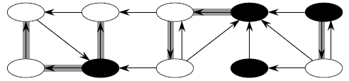
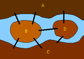
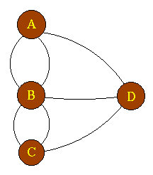
C1 C2 C3 C4
The above directed graph has 4 strongly connected components: C1, C2, C3 and C4. If G has an edge from some vertex in Ci to some vertex in Cj where i ≠ j, then one can reach any vertex in Cj from any vertex in Ci but not return. In the example, one can reach any vertex in C2 from any vertex in C1 but cannot return to C1 from C2.
The algorithm in CLRS for finding strongly connected components of G = (V, E) uses the transpose of G, which define as:
- GT = (V, ET), where ET = {(u, v): (v, u) ∈ E}.
- GT is G with all edges reversed.
From the given graph G, one can create GT in linear time (i.e., Θ(V + E)) if using adjacency lists.
Observation:
The graphs G and GT have the same SCC's. This means that vertices u and v are reachable from each other in G if and only if reachable from each other in GT.
Component Graph
The idea behind the computation of SCC comes from a key property of the component graph, which is defined as follows:
GSCC = (VSCC, ESCC), where VSCC has one vertex for each SCC in G and ESCC has an edge if there's an edge between the corresponding SCC's in G.
For our example (above) the GSCC is:
The key property of GSCC is that the component graph is a dag, which the following lemma implies.
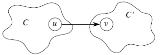
Lemma GSCC is a dag. More formally, let C and C' be distinct SCC's in G, let u, v in C, u', v' in C', and suppose there is a path u ↝ u' in G. Then there cannot also be a path v' ↝ v in G.
Proof Suppose there is a path v' ↝ v in G. Then there are paths u ↝ u' ↝ v' and v' ↝ v ↝ u in G. Therefore, u and v' are reachable from each other, so they are not in separate SCC's. This completes the proof.
ALGORITHM
A DFS(G) produces a forest of DFS-trees. Let C be any strongly connected component of G, let v be the first vertex on C discovered by the DFS and let T be the DFS-tree containing v when DFS-visit(v) is called all vertices in C are reachable from v along paths containing visible vertices; DFS-visit(v) will visit every vertex in C, add it to T as a descendant of v.
STRONGLY-CONNECTED-COMPONENTS (G)
1. Call DFS(G) to compute finishing times f[u] for all u.
2. Compute GT
3. Call DFS(GT), but in the main loop, consider vertices in order of decreasing f[u] (as computed in first DFS)
4. Output the vertices in each tree of the depth-first forest formed in second DFS as a separate SCC.
2. Compute GT
3. Call DFS(GT), but in the main loop, consider vertices in order of decreasing f[u] (as computed in first DFS)
4. Output the vertices in each tree of the depth-first forest formed in second DFS as a separate SCC.
Time: The algorithm takes linear time i.e., θ(V + E), to compute SCC of a digraph G.
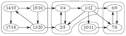
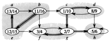
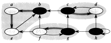
From our Example (above):
1. Do DFS
2. GT
3. DFS (roots blackened)
2. GT
3. DFS (roots blackened)
Another Example (CLRS) Consider a graph G = (V, E).
1. Call DFS(G)
2. Compute GT
3. Call DFS(GT) but this time consider the vertices in order to decreasing finish time.
4. Output the vertices of each tree in the DFS-forest as a separate strongly connected components.
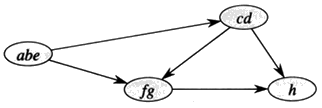
{a, b, e}, {c, d}, {f, g}, and {h}
Now the question is how can this possibly work?
Idea By considering vertices in second DFS in decreasing order of finishing times from first DFS, we are visiting vertices of the component graph in topological sort order.
To prove that it really works, first we deal with two notational issues:
- We will be discussing d[u] and f[u]. These always refer to the first DFS in the above algorithm.
- We extend notation for d and f to sets of vertices U subset V:
- d(U) = minu ∈ U {d[u]} (earliest discovery time of any vertex in U)
- f(U) = minu ∈ U {f[u]} (latest finishing time of any vertex in U)
Lemma Let C and C' be distinct SCC's in G = (V, E). Suppose there is an edge (u, v) ∈ E such that u ∈ C and v ∈ C'. Then f(C) > f(C').
Proof There are two cases, depending on which SCC had the first discovered vertex during the first DFS.
Case i. If d(C) > d(C'), let x be the first vertex discovered in C. At time d[x], all vertices in C and C' are white. Thus, there exist paths of white vertices from x to all vertices in C and C'.
By the white-path theorem, all vertices in C and C' are descendants of x in depth-first tree.
By the parenthesis theorem, we have f[x] = f(C) > f(C').
Case ii. If d(C) > d(C'), let y be the first vertex discovered in C'. At time d[y], all vertices in C' are white and there is a white path from y to each vertex in C. This implies that all vertices in C' become descendants of y. Again, f[y] = f(C').
At time d[y], all vertices in C are white.
By earlier lemma, since there is an edge (u, v), we cannot have a path from C' to C. So, no vertex in C is reachable from y. Therefore, at time f[y], all vertices in C are still white. Therefore, for all w in C, f[w] > f[y], which implies that f(C) > f(C').
This completes the proof.
Corollary Let C and C' be distinct SCC's in G = (V, E). Suppose there is an edge (u, v) ∈ ET where u ∈ C and v ∈ C'. Then f(C) < f(C').
Proof Edge (u, v) ∈ ET implies (v, u) ∈ E. Since SCC's of G and GT are the same, f(C') > f(C). This completes the proof.
Corollary Let C and C' be distinct SCC's in G = (V, E), and suppose that f(C) > f(C'). Then there cannot be an edge from C to C' in GT.
Proof Idea It's the contrapositive of the previous corollary.
Now, we have the intuition to understand why the SCC procedure works.
When we do the second DFS, on GT, start with SCC C such that f(C) is maximum. The second DFS starts from some x ∈ C, and it visits all vertices in C. Corollary says that since f(C) > f(C') for all C' ≠ C, there are no edges from C to C' in GT. Therefore, DFS will visit only vertices in C.
Which means that the depth-first tree rooted at x contains exactly the vertices of C.
The next root chosen in the second DFS is in SCC C' such that f(C') is maximum over all SCC's other than C. DFS visits all vertices in C', but the only edges out of C' go to C, which we've already visited.
Therefore, the only tree edges will be to vertices in C'.
We can continue the process.
Each time we choose a root for the second DFS, it can reach only
- vertices in its SCC ‾ get tree edges to these,
- vertices in SCC's already visited in second DFS ‾ get no tree edges to these.
We are visiting vertices of (GT)SCC in reverse of topologically sorted order. [CLRS has a formal proof.]
Before leaving strongly connected components, lets prove that the component graph of G = (V, E) is a directed acyclic graph.
Proof (by contradiction) Suppose component graph of G = (V, E) was not a DAG and G comprised of a cycle consisting of vertices v1, v2 , . . . , vn . Each vi corresponds to a strongly connected component (SCC) of component graph G. If v1, v2 , . . . , vn themselves form a cycle then each vi ( i runs from 1 to n) should have been included in the SCC corresponding to vj ( j runs from 1 to n and i ≠ j). But each of the vertices is a vertex from a difference SCC of G. Hence, we have a contradiction! Therefore, SCC of G is a directed acyclic graph.
Related Problems
1. Edge-vertex connectivity problem.
2. Shortest path problem.
2. Shortest path problem.
Euler Tour
The motivation of this section is derived from the famous Konigsberg bridge problem solved by Leonhard Euler in 1736. The 18th century German city of Königsberg was situated on the river Pregel. Within a park built on the banks of the river, there were two islands joined by seven bridges. The puzzle asks whether it is possible to take a tour through the park, crossing each bridge only once.
An exhaustive search requires starting at every possible point and traversing all the possible paths from that point - an O(n!) problem. However Euler showed that anEulerian path existed if and only if
- it is possible to go from any vertex to any other by following the edges (the graph must be connected) and
- every vertex must have an even number of edges connected to it, with at most two exceptions (which constitute the starting and ending points).
It is easy to see that these are necessary conditions: to complete the tour, one needs to enter and leave every point except the start and end points. The proof that these are sufficient conditions may be found in the literature . Thus we now have a O(n) problem to determine whether a path exists.
In order to get a solution transform the map into a graph in which the nodes represent the "dry land" points and the arcs represent the bridges.
We can now easily see that the Bridges of Königsberg does not have a solution. A quick inspection shows that it does have a Hamiltonian path.
Definition A Euler tour of a connected, directed graph G = (V, E) is a cycle that traverses each edge of graph G exactly once, although it may visit a vertex more than once.
In the first part of this section we show that G has an Euler tour if and only if in-degrees of every vertex is equal to out-degree vertex. In the second part, we describe an algorithm to find an Euler tour of graph if one exists.
Part 1 Show that G has an Euler tour if and only if in-degree(v) = out-degree(v) for each vertex vÎV
Proof
First we'll work with => direction.
We will call a cycle simple if it visits each vertex no more than once, and complex if can visit a vertex more than once. We know that each vertex in a simple cycle in-degree and out-degree one, and any complex cycles can be expressed as a union of simple cycles. This implies that any vertex in a complex cycle (and in particular an Euler tour) has in-degree equal to its out-degree. Thus, if a graph has an Euler tour than all of its vertices have equal in- and out- degrees.
Now look at the <= direction.
Suppose we have a connected graph for which the in-degree and out-degree of all vertices are equal. Let C be the longest complex cycle within G. If C is not an Euler tour, then there is a vertex v of G touched by C such that not all edges in and out v of are exhausted by C. We may construct a cycle C` in G-C starting and ending at v by performing a walk in G-C. (The reason is that G-C also has a property that in-degrees and out-degrees are equal.) this simply means that the complex cycle that starts at v goes along the edges of C` (returning to v) and then goes along the edges of C is a longer complex cycle than C. This contradicts our choice of C as the longest complex cycle which means that C must have been an Euler tour.
Part 2 Find an Euler tour of given graph G if one exists.
ALGORITHM
Given a starting vertex , the v0 algorithm will first find a cycle C starting and ending at v0 such that C contains all edges going into and out of v0. This can be performed by a walk in the graph. As we discover vertices in cycle C, we will create a linked list which contains vertices in order and such that the list begins and ends in vertex v0. We set the current painter to the head of the list. We now traverse the list by moving our pointer "current" to successive vertices until we and a vertex which has an outgoing edge which has not been discovered. (If we reach the end of the list, then we have already found the Euler tour). Suppose we find the vertex, vi, that has an undiscovered outgoing edge. We then take a walk beginning and ending at vi such that all undiscovered edges containing vi are contained in the walk. We insert our new linked list into old linked list in place of vi and more "current" to the new neighbor pointed to the first node containing vi. We continue this process until we search the final node of the linked list, and the list will then contains an Euler tour.
Running Time of Euler Tour
The algorithm traverse each edge at most twice, first in a walk and second while traversing the list to find vertices with outgoing edges. Therefore, the total running time of the algorithm is O(|E|).
Generic-Minimum Spanning Tree
A spanning tree of a graph G is a subgraph that is a tree and contains every vertex of G. Informally, the minimum spanning tree, MST, is to find a free tree T of a given graph G that contains all the vertices of G and has the minimum total weight of the edges of G over all such trees.
Problem
A town has set of houses and a set of roads. A road connects two and only two houses. A road connecting houses u and v has a repair cost w(u, v). The goal is to repair enough (and no more) roads such that
1. everyone stays connected: can reach every house from all other houses, and
2. total repair cost is minimum.
2. total repair cost is minimum.
Model as a Graph
Given undirected graph G = (V, E) and weight w(u, v) on each edge (u, v) ∈ E. The problem is to find T ⊆ E such that
1. T connects all vertices (T is a spanning tree), and
2. w(T) = ∑(u, v)∈T w(u, v) is minimized.
2. w(T) = ∑(u, v)∈T w(u, v) is minimized.
A spanning tree whose weight is minimum over all spanning trees is called a minimum spanning tree, or MST.
The example of such a graph is as follows:
Note that the edges in MST are shaded. In this example, there is more than one MST. Replace edge (e, f) by (c, e). We get a different spanning tree with the same weight.
Growing a minimum spanning tree
Some important properties of an MST are as follows:
- It has |V| − 1 edges.
- It has no cycles.
- It might not be unique.
Building up the Solution
- We will build a set A of edges.
- Initially, set A has no edges.
- As we add edges to the set A, maintain a loop invariant:
- Loop invariant: The set A is a subset of some MST.
- Add only edges that maintain the invariant. If a set A is a subset of some MST, an edge (u, v) is safe for A if and only if A ∪ {(u, v)} is also a subset of some MST. So, we will add only safe edges.
Generic MST Algorithm
There are several different methods for computing minimum spanning trees, but really they are all instances of the following generic algorithm.
GENERIC-MST (G, w)
A = { }
while A is not a spanning tree
do find an edge (u, v) that is safe for set A
A = A ∪ {(u, v)}
return A
while A is not a spanning tree
do find an edge (u, v) that is safe for set A
A = A ∪ {(u, v)}
return A
Use the loop invariant to show that this generic algorithm works.
Initialization: The empty set trivially satisfies the loop invariant.
Maintenance: Since we add only safe edges, set A remains a subset of some MST.
Termination: All edges added to the set A are in an MST, so when we stop, A is a spanning tree that is also an MST.
Maintenance: Since we add only safe edges, set A remains a subset of some MST.
Termination: All edges added to the set A are in an MST, so when we stop, A is a spanning tree that is also an MST.
Finding a Safe Edge
How do we find safe edges?
Let's look at the example. Edge (c, f) has the lowest weight of any edge in the graph. Is it safe for A = { }?
Intuitively: Let S ⊂ V be any set of vertices that includes c but not f (so that f is in V − S). In any MST, there has to be one edge (at least) that connects S with V − S. Why not choose the edge with minimum weight? (Which would be (c, f) in this case.)
Some definitions: Let S ⊂ V and A ⊆ E.
- A cut (S, V − S) is a partition of vertices into disjoint sets V and V − S.
- Edge (u, v) in E crosses cut (S, V − S) if one endpoint is in S and the other is in V − S.
- A cut respects A if and only if no edge in A crosses the cut.
- An edge is a light edge crossing a cut if and only if its weight is minimum over all edges crossing the cut. For a given cut, there can be more than one light edge crossing it.
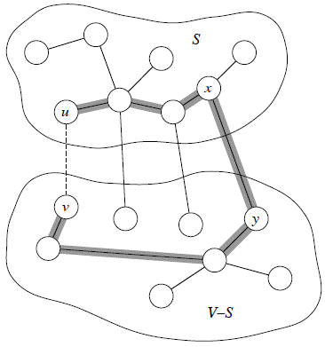
Theorem Let A be a subset of some MST, (S, V − S) be a cut that respects A, and (u, v) be a light edge crossing (S, V − S). Then (u, v) is safe for A.
Proof Let T be an MST that includes A.
If T contains an edge (u, v), we are done.
So now assume that T does not contain (u, v). We will construct a different MST T that include A = A ∪ {(u, v)}.
Recall: a tree has unique path between each pair of vertices. Since T is an MST, it contains a unique path p between u and v. Path p must cross the cut (S, V − S) at least once. Let (x, y) be an edge of p that crosses the cut. From how we chose (u, v), must have w(u, v) < w(x, y).
[Note carefully: Except for the dashed edge (u, v), all edges shown are in T. A is some subset of the edges of T, but A cannot contain any edges that cross the cut (S, V − S), since this cut respects A. Shaded edges are the path p.]
Since the cut respects A, edge (x, y) is not in A.
To form T' from T:
- Remove the edge (x, y). Breaks T into two components.
- Add edge (u, v). Reconnects.
So T' = T − {(x, y)} ∪ {(u, v)}.
T' is a spanning tree.
w(T') = w(T) − w(x, y) + w(u, v)
≤ w(T),
since w(u, v) ≤ w(x, y). Since T' is a spanning tree, w(T') ≤ w(T), and T is an MST, then T' must be an MST.
We need to show that edge (u, v) is safe for the set A:
- A ⊆ T and (x, y) ∉ A ⇒ A ⊆ T'.
- A ∪ {(u, v)} ⊆ T'.
- Since T' is an MST, edge (u, v) is safe for the set A.
This completes the proof.
So, in GENERIC-MST:
- A is a forest containing connected components into one. Initially, each component is a single vertex.
- Any safe edge merges two of these components into one. Each components is a tree.
- Since an MST has exactly |V| − 1 edges, the for loop iterates |V| − 1 times. Equivalently, after adding |V| − 1 safe edges, we're down to just one components.
Corollary If C = (VC, EC) is a connected component in the forest GA = (V, A) and (u, v) is a light edge connecting C to some other component in GA [i.e., (u, v) is a light edge crossing the cut (VC, V − VC)], then (u, v) is safe for A.
Proof Set S = VC in the theorem. And this completes the proof.
This is naturally leads to the algorithm called Kruskal's algorithm to solve the minimum-spanning -tree problem.
Kruskal's Algorithm
This minimum spanning tree algorithm was first described by Kruskal in 1956 in the same paper where he rediscovered Jarnik's algorithm. This algorithm was also rediscovered in 1957 by Loberman and Weinberger, but somehow avoided being renamed after them. The basic idea of the Kruskal's algorithms is as follows: scan all edges in increasing weight order; if an edge is safe, keep it (i.e. add it to the set A).
Overall Strategy
Kruskal's Algorithm, as described in CLRS, is directly based on the generic MST algorithm. It builds the MST in forest. Initially, each vertex is in its own tree in forest. Then, algorithm consider each edge in turn, order by increasing weight. If an edge (u, v) connects two different trees, then (u, v) is added to the set of edges of the MST, and two trees connected by an edge (u, v) are merged into a single tree on the other hand, if an edge (u, v) connects two vertices in the same tree, then edge (u, v) is discarded.
A little more formally, given a connected, undirected, weighted graph with a function w : E → R.
- Starts with each vertex being its own component.
- Repeatedly merges two components into one by choosing the light edge that connects them (i.e., the light edge crossing the cut between them).
- Scans the set of edges in monotonically increasing order by weight.
- Uses a disjoint-set data structure to determine whether an edge connects vertices in different components.
Data Structure
Before formalizing the above idea, lets quickly review the disjoint-set data structure from Chapter 21.
- Make_SET(v): Create a new set whose only member is pointed to by v. Note that for this operation v must already be in a set.
- FIND_SET(v): Returns a pointer to the set containing v.
- UNION(u, v): Unites the dynamic sets that contain u and v into a new set that is union of these two sets.
Algorithm
Start with an empty set A, and select at every stage the shortest edge that has not been chosen or rejected, regardless of where this edge is situated in the graph.
KRUSKAL(V, E, w)
A ← { } ▷ Set A will ultimately contains the edges of the MST
for each vertex v in V
do MAKE-SET(v)
sort E into nondecreasing order by weight w
for each (u, v) taken from the sorted list
do if FIND-SET(u) = FIND-SET(v)
then A ← A ∪ {(u, v)}
UNION(u, v)
return A
for each vertex v in V
do MAKE-SET(v)
sort E into nondecreasing order by weight w
for each (u, v) taken from the sorted list
do if FIND-SET(u) = FIND-SET(v)
then A ← A ∪ {(u, v)}
UNION(u, v)
return A
Illustrative Examples
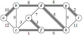
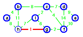
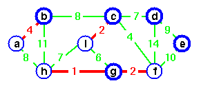
Lets run through the following graph quickly to see how Kruskal's algorithm works on it:
We get the shaded edges shown in the above figure.
Edge (c, f) : safe
Edge (g, i) : safe
Edge (e, f) : safe
Edge (c, e) : reject
Edge (d, h) : safe
Edge (f, h) : safe
Edge (e, d) : reject
Edge (b, d) : safe
Edge (d, g) : safe
Edge (b, c) : reject
Edge (g, h) : reject
Edge (a, b) : safe
Edge (g, i) : safe
Edge (e, f) : safe
Edge (c, e) : reject
Edge (d, h) : safe
Edge (f, h) : safe
Edge (e, d) : reject
Edge (b, d) : safe
Edge (d, g) : safe
Edge (b, c) : reject
Edge (g, h) : reject
Edge (a, b) : safe
At this point, we have only one component, so all other edges will be rejected. [We could add a test to the main loop of KRUSKAL to stop once |V| − 1 edges have been added to A.]
Note Carefully: Suppose we had examined (c, e) before (e, f ). Then would have found (c, e) safe and would have rejected (e, f ).
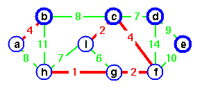
Example (CLRS) Step-by-Step Operation of Kurskal's Algorithm.
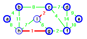
Step 1. In the graph, the Edge(g, h) is shortest. Either vertex g or vertex h could be representative. Lets choose vertex g arbitrarily.
Step 2. The edge (c, i) creates the second tree. Choose vertex c as representative for second tree.
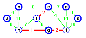
Step 3. Edge (g, g) is the next shortest edge. Add this edge and choose vertex g as representative.
Step 4. Edge (a, b) creates a third tree.
Step 5. Add edge (c, f) and merge two trees. Vertex c is chosen as the representative.
Step 6. Edge (g, i) is the next next cheapest, but if we add this edge a cycle would be created. Vertex c is the representative of both.
Step 7. Instead, add edge (c, d).
Step 8. If we add edge (h, i), edge(h, i) would make a cycle.
Step 9. Instead of adding edge (h, i) add edge (a, h).
Step 10. Again, if we add edge (b, c), it would create a cycle. Add edge (d, e) instead to complete the spanning tree. In this spanning tree all trees joined and vertex c is a sole representative.
Analysis
Initialize the set A: O(1)
First for loop: |V| MAKE-SETs
Sort E: O(E lg E)
Second for loop: O(E) FIND-SETs and UNIONs
- Assuming the implementation of disjoint-set data structure, already seen in Chapter 21, that uses union by rank and path compression: O((V + E) α(V)) + O(E lg E)
- Since G is connected, |E| ≥ |V| − 1⇒ O(E α(V)) + O(E lg E).
- α(|V|) = O(lg V) = O(lg E).
- Therefore, total time is O(E lg E).
- |E| ≤ |V|2 ⇒lg |E| = O(2 lg V) = O(lg V).
- Therefore, O(E lg V) time. (If edges are already sorted, O(E α(V)), which is almost linear.)
II Kruskal's Algorithm Implemented with Priority Queue Data Structure
MST_KRUSKAL(G)
for each vertex v in V[G]
do define set S(v) ← {v}
Initialize priority queue Q that contains all edges of G, using the weights as keys
A ← { } ▷ A will ultimately contains the edges of the MST
while A has less than n − 1 edges
do Let set S(v) contains v and S(u) contain u
if S(v) ≠ S(u)
then Add edge (u, v) to A
Merge S(v) and S(u) into one set i.e., union
return A
Analysis
The edge weight can be compared in constant time. Initialization of priority queue takes O(E lg E) time by repeated insertion. At each iteration of while-loop, minimum edge can be removed in O(log E) time, which is O(log V), since graph is simple. The total running time is O((V + E) log V), which is O(E lg V) since graph is simple and connected.
Jarnik's (Prim's) Algorithm
The oldest and simplest MST algorithm was discovered by Boruvka in 1926. The Boruvka's algorithm was rediscovered by Choquet in 1938; again by Florek, Lukaziewicz, Perkal, Stienhaus, and Zubrzycki in 1951; and again by Sollin in early 1960's. The next oldest MST algorithm was first described by the Polish mathematician Vojtech Jarnik in a 1929 letter to Boruvka. The algorithm was independently rediscovered by Kruskal in 1956, by Prim in 1957, by Loberman and Weinberger in 1957, and finally by Dijkstra in 1958. This algorithm is (inappropriately) called Prim's algorithm, or sometimes (even more inappropriately) called 'the Prim/Dijkstra algorithm'. The basic idea of the Jarnik's algorithm is very simple: find A's safe edge and keep it (i.e. add it to the set A).
Overall Strategy
Like Kruskal's algorithm, Jarnik's algorithm, as described in CLRS, is based on a generic minimum spanning tree algorithm. The main idea of Jarnik's algorithm is similar to that of Dijkstra's algorithm for finding shortest path in a given graph. The Jarnik's algorithm has the property that the edges in the set A always form a single tree. We begin with some vertex v in a given graph G =(V, E), defining the initial set of vertices A. Then, in each iteration, we choose a minimum-weight edge (u, v), connecting a vertex v in the set A to the vertex u outside of set A. Then vertex u is brought in to A. This process is repeated until a spanning tree is formed. Like Kruskal's algorithm, here too, the important fact about MSTs is that we always choose the smallest-weight edge joining a vertex inside set A to the one outside the set A. The implication of this fact is that it adds only edges that are safe for A; therefore when the Jarnik's algorithm terminates, the edges in set A form a minimum spanning tree, MST.
Details
- The Jarnik's algorithm builds one tree, so A is always a tree.
- It starts from an arbitrary "root" r.
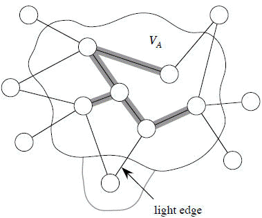
- At each step, find a light edge crossing cut (VA, V − VA), where VA = vertices that A is incident on. Add this edge to A.
Note that the edges of A are shaded.
Now the question is how to find the light edge quickly?
Use a priority queue Q:
- Each object is a vertex in V − VA.
- Key of v is minimum weight of any edge (u, v), where u ∈ VA.
- Then the vertex returned by EXTRACT-MIN is v such that there exists u ∈ VA and (u, v) is light edge crossing (VA, V − VA).
- Key of v is ∞ if v is not adjacent to any vertices in VA.
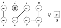
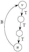
The edges of A will form a rooted tree with root r :
- Root r is given as an input to the algorithm, but it can be any vertex.
- Each vertex knows its parent in the tree by the attribute π[v] = parent of v. Initialize π[v] = NIL if v = r or v has no parent.
- As algorithm progresses, A = {(v, π[v]) : v ∈ V − {r} − Q}.
- At termination, VA = V ⇒ Q = ∅, so MST is A = {(v, π[v]) : v ∈ V − {r}}.
Algorithm
Choose a node and build a tree from there selecting at every stage the shortest available edge that can extend the tree to an additional node.
JARNIK(V, E, w, r )
Q ← { }
for each u in V
do key[u] ← ∞
π[u] ← NIL
INSERT(Q, u)
DECREASE-KEY(Q, r, 0) ▷ key[r ] ← 0
while Q is not empty
do u ← EXTRACT-MIN(Q)
for each v in Adj[u]
do if v in Q and w(u, v) < key[v]
then π[v] ← u
DECREASE-KEY(Q, v, w(u, v))
for each u in V
do key[u] ← ∞
π[u] ← NIL
INSERT(Q, u)
DECREASE-KEY(Q, r, 0) ▷ key[r ] ← 0
while Q is not empty
do u ← EXTRACT-MIN(Q)
for each v in Adj[u]
do if v in Q and w(u, v) < key[v]
then π[v] ← u
DECREASE-KEY(Q, v, w(u, v))
Illustrative Example
Do example from CLRS page 571.
Analysis
The performance of Jarnik's algorithm depends on how the priority queue is implemented:
- Suppose Q is a binary heap.
Initialize Q and first for loop: O(V lg V)
Decrease key of r : O(lg V)
while loop: |V| EXTRACT-MIN calls → O(V lg V)
≤ |E| DECREASE-KEY calls implies → that O(E lg V)
Total: O(E lg V)
- Suppose we could do DECREASE-KEY in O(1) amortized time.
Then ≤ |E| DECREASE-KEY calls take O(E) time altogether → total time becomes O(V lg V + E).
In fact, there is a way to do DECREASE-KEY in O(1) amortized time: Fibonacci heaps, in Chapter 20.
In depth Complexity Analysis of Jarnik's Algorithm
But before we start the analysis, recall some definitions from graph theory. Sparse graphs are those for which |E| is much less than |V|2 i.e., |E| << |V|2, we preferred the adjacency-list representation of the graph in this case. On the other hand, dense graphs are those for which |E| is close to |V|2 i.e., |E| ≈ ||V|2. In this case, we like to represent graph with adjacency-matrix representation.
As we have mentioned above, the performance of Jarnik's algorithm depends of how we choose to implement the priority queue Q.
- When a Q is implemented as a binary heap
We can use the BULID_HEAP procedure to perform the initialization in lines 1-4 in O(|V|) time. The while-loop in lines 6-11 is executed |V| times, and since each EXTRACT_MIN operation takes O(lg|V|) time, the total time for all calls to EXTRACT_MIN operation is O(|V| lg |V|). The for-loop in lines 8-11 is executed O(|E|) times altogether, since the sum of the lengths of all adjacency lists is 2|E|. Within the for-loop, the test for membership in Q in line 9 can be implemented in constant time by keeping a bit for each vertex that tells whether or not it is in Q, and updating the bit when the vertex is removed from Q. The assignment in line 11 involves an implicit DECREASE_KEY operation on the heap, which takes O(lg |V|) time with a binary heap. Thus, the total time for Jarnik's algorithm using a binary heap is O(|V| lg|V| + |E| lg |V|). - When Q is implemented as a Fibonacci heap
In this case, the performance of the DECREASE_KEY operation implicitly called in line 11 will be improved. Instead of taking O(lg|V|) time, with a Fibonacci heap of |V| elements, the DECREASE_KEY operation will take O(1) amortized time. With a Fibonacci heap, an EXTRACT_MIN operation takes O(lg |V|) amortized time. Therefore, the total time for Jarnik's algorithm using a Fibonacci heap to implement the priority queue Q is O(|V| lg |V| + |E|). - When graph G = (V, E) is sparse i.e., |E| = Θ(|V|)
From above description, it can be seen that both versions of Jarnik's algorithm will have the running time O(|V| lg |V|). Therefore, the Fibonacci-heap implementation will not make Jarnik's algorithm asymptotically faster for sparse graph. - When graph G is dense, i.e., |E| = Θ(|V|)
From above description, we can see that Jarnik's algorithm with the binary heap will take |V|2 lg |V| time whereas Jarnik's algorithm with Fibonacci-heap will take |V|2. Therefore, the Fibonacci-heap implementation does not make Jarnik's algorithm asymptotically faster for dense graphs. - Comparing the time complexities of the two versions of Jarnik's algorithms, mentioned in (a) and (b), we can see that |E| is greater than |V|, the Jarnik's algorithm with the Fibonacci-heap implementation will be asymptotically faster than the one with the binary-heap implementation.
The time taken by the Jarnik's algorithm is determined by the speed of the queue operations. With the queue implemented as a Fibonacci heap, it takes O(E + V lg V) time.
Since the keys in the priority queue are edge weights, it might be possible to implement the queue even more efficiently when there are restrictions on the possible edge weights.
We can improve the running time of Jarnik's algorithm if W is a constant by implementing the queue as an array Q[0 . .W + 1] (using the W + 1 slot for key = ∞), where each slot holds a doubly linked list of vertices with that weight as their key. Then EXTRACT-MIN takes only O(W) = O(1) time (just scan for the first nonempty slot), and DECREASE-KEY takes only O(1) time (just remove the vertex from the list its in and insert it at the front of the list indexed by the new key). This gives a total running time of O(E), which is the best possible asymptotic time (since Ω(E) edges must be processed).
However, if the range of edge weights is 1 to |V|, then EXTRACT-MIN takes Θ(V) time with this data structure. So the total time spent doing EXTRACT-MIN is Θ(V2), slowing the algorithm to Θ(E + V2) = (V2). In this case, it is better to keep the Fibonacci-heap priority queue, which gave the Θ(E + V lg V) time.
However, if the range of edge weights is 1 to |V|, then EXTRACT-MIN takes Θ(V) time with this data structure. So the total time spent doing EXTRACT-MIN is Θ(V2), slowing the algorithm to Θ(E + V2) = (V2). In this case, it is better to keep the Fibonacci-heap priority queue, which gave the Θ(E + V lg V) time.
There are data structures not in the CLRS that yield better running times:
- The van Emde Boas data structure (mentioned in the chapter notes for Chapter 6 and the introduction to Part V) gives an upper bound of O(E + V lg lg V) time for Jarnik's algorithm.
- A redistributive heap (used in the single-source shortest-paths algorithm of Ahuja, Mehlhorn, Orlin, and Tarjan, and mentioned in the chapter notes for Chapter 24) gives an upper bound of O(E + V √lg V) for Jarnik's algorithm.
Jarnik's Algorithm with Adjacency Matrix
Now we describe the Jarnik's algorithm when the graph G = (V, E) is represented as an adjacency matrix. Instead of heap structure, we'll use an array to store the key of each node.
1. A ← V[G] ▷ Array
2. for each vertex u in Q
3. do key [u] ← ∞
4. key [r] ← 0
5. π[r] ← NIL
6. while array A is empty
7. do scan over A find the node u with smallest key, and remove it from array A
8. for each vertex v in Adj[u]
9. if v is in A and w[u, v] < key[v]
10. then π[v] ← u
11. key[v] ← w[u, v]
2. for each vertex u in Q
3. do key [u] ← ∞
4. key [r] ← 0
5. π[r] ← NIL
6. while array A is empty
7. do scan over A find the node u with smallest key, and remove it from array A
8. for each vertex v in Adj[u]
9. if v is in A and w[u, v] < key[v]
10. then π[v] ← u
11. key[v] ← w[u, v]
Analysis
For-loop (line 8-11) takes O(deg[u]) since line 10 and 11 take constant time. Due to scanning whole array A, line 7 takes O(V) time and lines 1-5, clearly take (V).
Therefore, the while-loop (lines 6-11) needs
Therefore, the while-loop (lines 6-11) needs
Ο(∑u(V + deg[u])) = Ο(V2 + E)
= Ο(V2)
= Ο(V2)
Single Source Shortest Path
Suppose G be a weighted directed graph where a minimum labeled w(u, v) associated with each edge (u, v) in E, called weight of edge (u, v). These weights represent the cost to traverse the edge. A path from vertex u to vertex v is a sequence of one or more edges.
<(v1,v2), (v2,v3), . . . , (vn-1, vn)> in E[G] where u = v1 and v = vn
The cost (or length or weight) of the path P is the sum of the weights of edges in the sequence.
The shortest-path weight from a vertex uÎV to a vertex vÎV in the weighted graph is the minimum cost of all paths from u to v. If there exists no such path from vertex u to vertex v then the weight of the shortest-path is ∞.
Variant of single-source shortest problems
- Given a source vertex, in the weighted diagraph, find the shortest path weights to all other vertices in the digraph.
- Given a destination vertex, t, in the weighted digraph, find the shortest path weights from all other vertices in the digraph.
- Given any two vertices in the weighted digraph, find the shortest path (from u to v or v to u).
Negative-Weight Edges
The negative weight cycle is a cycle whose total is negative. No path from starting vertex S to a vertex on the cycle can be a shortest path. Since a path can run around the cycle many, many times and get any negative cost desired. in other words, a negative cycle invalidates the noton of distance based on edge weights.
Relaxation Technique
This technique consists of testing whether we can improve the shortest path found so far if so update the shortest path. A relaxation step may or may not decrease the value of the shortest-path estimate.
The following code performs a relaxation step on edge(u,v).
Relax (u, v, w)
If d[u] + w(u, v) < d[v]
then d[v] d[u] + w[u, v]
Diagram
Single Source Shortest Problem
Given a weighted graph G, find a shortest path from given vertex to each other vertex in G. Note that we can solve this problem quite easily with BFS traversal algorithm in the special case when all weights are 1. The greedy approach to this problem is repeatedly selecting the best choice from those available at that time.
Dijkstra's Algorithm
Dijkstra's algorithm solves the single-source shortest-path problem when all edges have non-negative weights. It is a greedy algorithm and similar to Prim's algorithm. Algorithm starts at the source vertex, s, it grows a tree, T, that ultimately spans all vertices reachable from S. Vertices are added to T in order of distance i.e., first S, then the vertex closest to S, then the next closest, and so on. Following implementation assumes that graph G is represented by adjacency lists.
DIJKSTRA (G, w, s)
- INITIALIZE SINGLE-SOURCE (G, s)
- S ← { } // S will ultimately contains vertices of final shortest-path weights from s
- Initialize priority queue Q i.e., Q ← V[G]
- while priority queue Q is not empty do
- u ← EXTRACT_MIN(Q) // Pull out new vertex
- S ← S È {u}
// Perform relaxation for each vertex v adjacent to u- for each vertex v in Adj[u] do
- Relax (u, v, w)
Analysis
Like Prim's algorithm, Dijkstra's algorithm runs in O(|E|lg|V|) time.
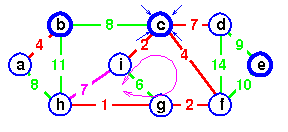
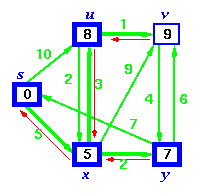
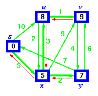
Example: Step by Step operation of Dijkstra algorithm.
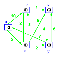
Step1. Given initial graph G=(V, E). All nodes nodes have infinite cost except the source node, s, which has 0 cost.
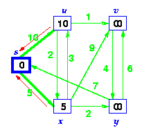
Step 2. First we choose the node, which is closest to the source node, s. We initialize d[s] to 0. Add it to S. Relax all nodes adjacent to source, s. Update predecessor (see red arrow in diagram below) for all nodes updated.
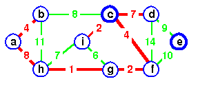
Step 3. Choose the closest node, x. Relax all nodes adjacent to node x. Update predecessors for nodes u, v and y (again notice red arrows in diagram below).
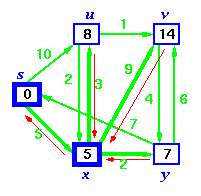
Step 4. Now, node y is the closest node, so add it to S. Relax node v and adjust its predecessor (red arrows remember!).
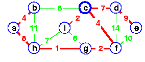
Step 5. Now we have node u that is closest. Choose this node and adjust its neighbor node v.
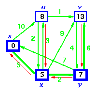
Step 6. Finally, add node v. The predecessor list now defines the shortest path from each node to the source node, s.
Q as a linear array
EXTRACT_MIN takes O(V) time and there are |V| such operations. Therefore, a total time for EXTRACT_MIN in while-loop is O(V2). Since the total number of edges in all the adjacency list is |E|. Therefore for-loop iterates |E| times with each iteration taking O(1) time. Hence, the running time of the algorithm with array implementation is O(V2 + E) = O(V2).
Q as a binary heap ( If G is sparse)
In this case, EXTRACT_MIN operations takes O(lg V) time and there are |V| such operations.
The binary heap can be build in O(V) time.
Operation DECREASE (in the RELAX) takes O(lg V) time and there are at most such operations.
Hence, the running time of the algorithm with binary heap provided given graph is sparse is O((V + E) lg V). Note that this time becomesO(ElgV) if all vertices in the graph is reachable from the source vertices.
Q as a Fibonacci heap
In this case, the amortized cost of each of |V| EXTRAT_MIN operations if O(lg V).
Operation DECREASE_KEY in the subroutine RELAX now takes only O(1) amortized time for each of the |E| edges.
As we have mentioned above that Dijkstra's algorithm does not work on the digraph with negative-weight edges. Now we give a simple example to show that Dijkstra's algorithm produces incorrect results in this situation. Consider the digraph consists of V = {s, a, b} and E = {(s, a), (s, b), (b, a)} where w(s, a) = 1, w(s, b) = 2, and w(b, a) = -2.
Dijkstra's algorithm gives d[a] = 1, d[b] = 2. But due to the negative-edge weight w(b, a), the shortest distance from vertex s to vertex a is 1-2 = -1.
Bellman-Ford Algorithm
Bellman-Ford algorithm solves the single-source shortest-path problem in the general case in which edges of a given digraph can have negative weight as long as G contains no negative cycles.
This algorithm, like Dijkstra's algorithm uses the notion of edge relaxation but does not use with greedy method. Again, it uses d[u] as an upper bound on the distance d[u, v] from u to v.
The algorithm progressively decreases an estimate d[v] on the weight of the shortest path from the source vertex s to each vertex v in V until it achieve the actual shortest-path. The algorithm returns Boolean TRUE if the given digraph contains no negative cycles that are reachable from source vertex s otherwise it returns Boolean FALSE.
BELLMAN-FORD (G, w, s)
- INITIALIZE-SINGLE-SOURCE (G, s)
- for each vertex i = 1 to V[G] - 1 do
- for each edge (u, v) in E[G] do
- RELAX (u, v, w)
- For each edge (u, v) in E[G] do
- if d[u] + w(u, v) < d[v] then
- return FALSE
- return TRUE
Analysis
- The initialization in line 1 takes
 (v) time
 - For loop of lines 2-4 takes O(E) time and For-loop of line 5-7 takes O(E) time.


0 comments